


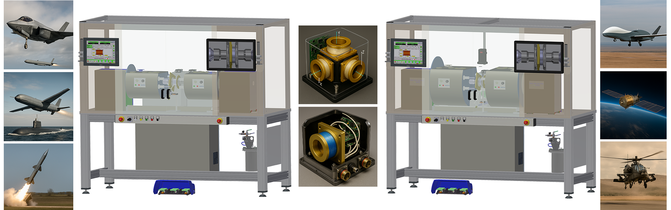
🌀 RWC201-Q1/Q2-FOG – High-Precision Winding Technology for FOG Coils
The RWC201-Q1/Q2-FOG is a specialized winding machine for producing high-quality coils for fiber optic gyroscopes (FOG). It is designed for defined quadrupolar and octupolar winding processes and enables tension-controlled, reproducible and process-reliable fiber placement.
Depending on the machine configuration, fiber type and spool geometry, the system can be configured for different optical fiber diameters and product dimensions. The final specification is defined on a project-specific basis.
🌐 Flexible Winding Processes
The machine operates with two rotating winding units on the left and right side. This enables demanding layer windings for quadrupolar and octupolar winding processes.
- recipe-controlled winding sequences
- controlled fiber placement from the left and right supply spool
- suitable for symmetrical FOG winding geometries
🔄 Winding Behavior & Operator Convenience
The winding principle follows a recipe-controlled, alternating process sequence. Depending on the process, the winding units operate alternately in order to support controlled and reproducible layer formation.
Functions such as slow start, precise stopping, fine adjustment or speed-controlled winding can be conveniently carried out via touchscreen, joystick or foot control.
⚙️ System Note: RWC042-F as Preparation Unit
The final FOG product coil is produced from two prepared supply spools. The preparation of these master/slave spools is carried out on a separate preparation unit, e.g. the RWC042-F. The RWC201-Q1/Q2-FOG subsequently performs the final precision winding process onto the product spool.
As a result, the main machine remains available for the actual FOG winding process, while the time-intensive fiber length preparation is carried out on the RWC042-F. The machine time of the RWC201-Q1/Q2-FOG is therefore used specifically for the value-adding final winding process.
More about the RWC042-F Preparation Unit🧵 Fiber Guidance & Traverse Unit
The traverse unit provides precise fiber guidance (pitch control) via a high-resolution traverse system. Fiber position, pitch, reversal points, start/stop ramps and direction of rotation are defined by the winding program.
- mechanical traverse accuracy depends on mechanical design, calibration and process conditions
- high-resolution software parameterization of the traverse movement
- layer-oriented and tension-controlled fiber placement
🎥 Monitoring & Quality Assurance
The winding surface can be monitored by video camera in order to detect irregularities at an early stage. Optionally, a digital microscope, laser scanning, adhesive application and UV curing process can be integrated.
Depending on the configuration, wound layers can be monitored by sensors and corrected depending on the process requirements.
🖥️ Control System & Program Data
Machine control is based on an industrial PC with touchscreen user interface. Winding programs can be stored and transferred locally, via USB or via network.
- recipe-based program management
- winding program editor, Excel import or WiDaMa system possible
- digital I/O interfaces for external components
- PLC integration possible on a project-specific basis
🔧 Expansion Options
Depending on the process requirements, the RWC201-Q1/Q2-FOG can be expanded with additional system components.
- digital microscope with autofocus and measuring function
- automatic adhesive application system
- laser flange scanning with reversal point correction
- laser monitoring of the winding surface
- fume extraction system
- LED lighting system
- touchscreen upgrade to 21.5″ or 24″
⚙️ System Advantage through Separate Process Steps
The RAWITEC system concept separates the preparation of the optical fiber from the final FOG winding process. The RWC042-F handles defined length preparation as well as the production of the master and slave supply spools. The RWC201-Q1/Q2-FOG is then used for the actual precision winding process of the final FOG product coil.
This prevents the main machine from being occupied by preparatory rewinding processes. Production time on the RWC201-Q1/Q2-FOG can be used specifically for the value-adding final winding process. At the same time, process risks can be reduced because length preparation and final coil winding are carried out separately, in a controlled and reproducible manner.
🇩🇪 Made in Germany as a Technical Advantage
The machine system consisting of RWC201-Q1/Q2-FOG and RWC042-F combines European special-purpose machine engineering expertise with flexible process design, precise fiber guidance and structured software and recipe management.
For demanding applications in FOG technology, sensor technology, navigation technology, aerospace, research and safety-critical high-tech sectors, RAWITEC offers a scalable system solution for the reproducible production of high-quality FOG coils.
✅ Conclusion
The RWC201-Q1/Q2-FOG combines precise winding technology, process-related monitoring, convenient operation and a flexible system architecture. It is suitable for the reproducible production of high-quality FOG coils in research, aerospace, sensor technology and other high-tech applications.
* Technical changes, dimensional modifications and design adaptations reserved.
RWC201-Q1 / Q2 – Technical Data
| Feature | Unit | RWC201-Q1-FOG | RWC201-Q2-FOG |
|---|---|---|---|
| Fiber range | µm | 50 – 200 (coated) | 80 – 250 (coated) |
| Fiber length | m | 50 – 5000 | 100 – 8000 |
| Clamping length | mm | 200 * | 260 * |
| Max. pitch-traverse | mm | 99 / Spindle Turn³ | 99 / Spindle Turn³ |
| Optional: Autofocus Microscope | Digital microscope with measurement | ||
| Optional: Glue System | Automatic glue dispensing system | ||
| Optional: Laser Flange Sensing | With auto reversal correction | ||
| Optional: Fume Extraction | Fume extraction system | ||
| Optional: Surface Monitoring | Laser monitoring with auto layer correction | ||
| Belt Level | 1 | 1 | |
| Level 1 – Rotation speed | rpm | max 500 (limited to 50–100 rpm) | max 500 (limited to 50–100 rpm) |
| Level 1 – Torque | Nm | max 30.5 | max 42 |
| Wind Types | Wet or Dry | Wet or Dry | |
| Max Coil Height | mm | 90 | 125 |
| Max Coil Diameter | mm/inch | 180 * | 250 * |
| Center height (from table) | mm/inch | 250 **** | 250 **** |
| Tension Control (winding unit) | cN | 5 – 60 ** | 5 – 60 ** |
| PC Control | Industrial PC, Dual-Core 1 GHz / 2 GB RAM ** | ||
| Languages | DE, EN, AL, IT, FR, ES, CS, HU, SU, RU, PL, NL, EL, PT, ZH... *** | ||
| Connections | USB, Ethernet, Serial RS232, VGA, foot control, digital I/O (up to 64), PS2 | ||
| Operating System | Robust real-time OS | ||
| Backup / Update | Via USB and Ethernet | ||
| Printer Connection | USB ** | ||
| Digital/Analog I/O | Expandable *** | ||
| Display | 15" touch screen std., IP65 12–24" variants ** | ||
| Keyboard | USB wireless keyboard 2.4 GHz ** | ||
| Disk | iSATA-DOM 16 GB (expandable), up to 20,000 winding programs *** | ||
| PLC Interface | Integrated, for external component control ** | ||
| Joystick | Teach mode, CW/CCW, guide axis left/right | ||
| Software/Hardware Options | High flexibility and reliability | ||
| Connection Values | kVA | 3.8 | 3.9 |
| Dimensions (W×L×H) | mm | 1980×885×1754 | 2030×910×1754 |
| Power Supply | AC | 3×400 V – 50 Hz / 16 A | 3×400 V – 50 Hz / 16 A |
| Weight | kg | 486 | 515 |
** Optional, on request
*** Expandable on request
**** Optional – partial stroke, center height
² Approx. 400 KB per program (ca. 500 steps), incl. comments
³ Condition: main spindle speed × feed rate < 3600/min
Intuitive Touch Software for Winding Machines – Powerful & Versatile
The user interface was specially developed for intuitive and efficient touch operation on winding machines.
In addition to essential functions such as Open, Save, Copy, Delete, Edit, and Print winding programs, the software offers numerous advanced features:
- Integrated language switch for international use
- Extensive configuration options
- Service-relevant diagnostic tools
- Tools for system optimization and machine customization
Thanks to its clearly structured interface, the software supports both machine operators in daily production and technical staff during machine configuration and customization.
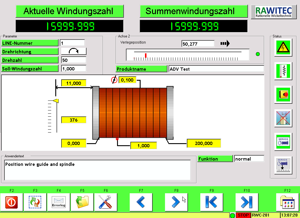 Home screen – central user interface
|
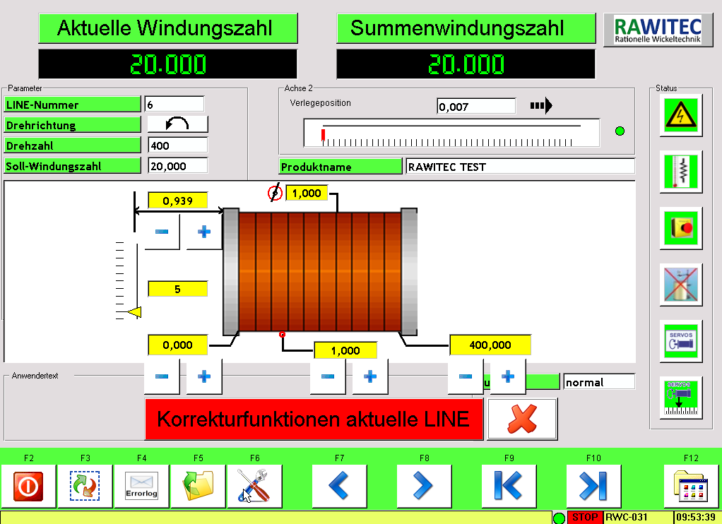 Display of main winding parameters and activated setup functions
|
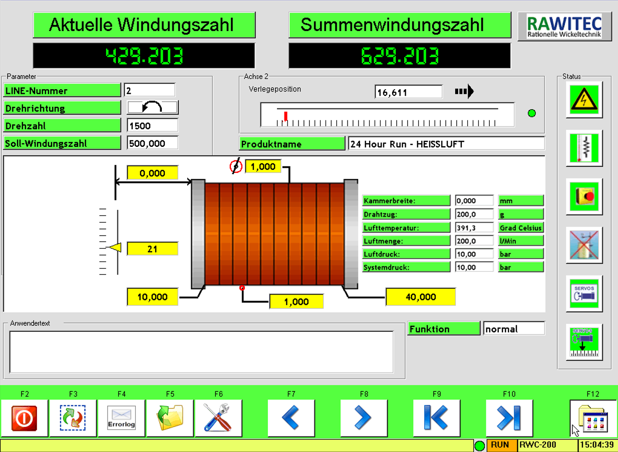 Display of main winding parameters and special functions
|
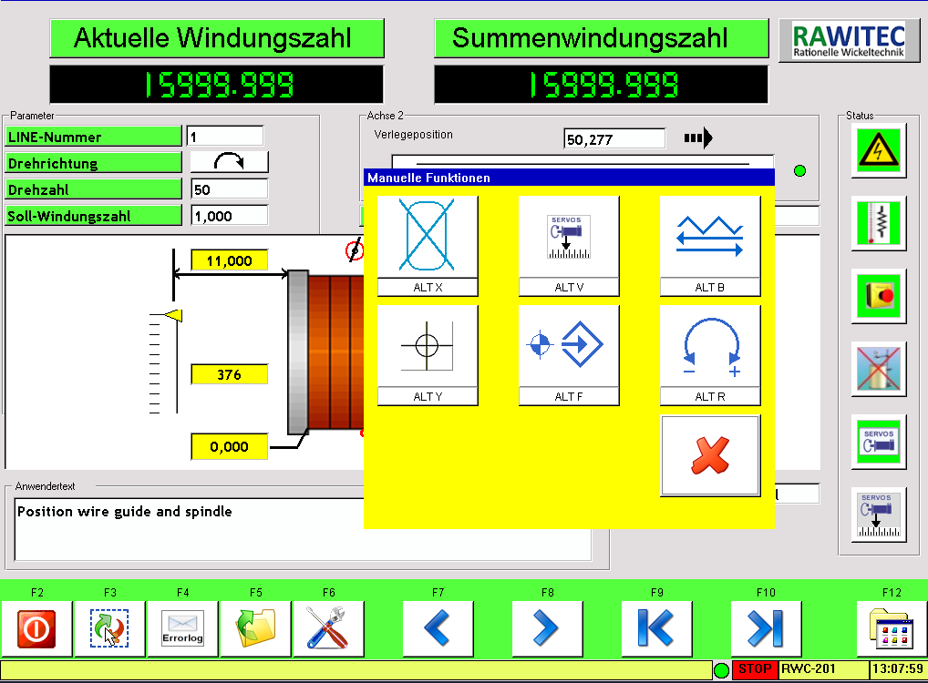 Manual functions
|
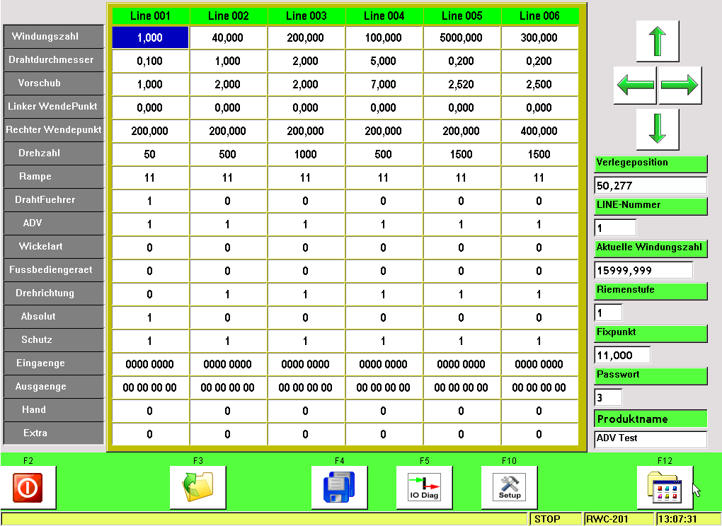 Programming page for entering all relevant winding parameters
|
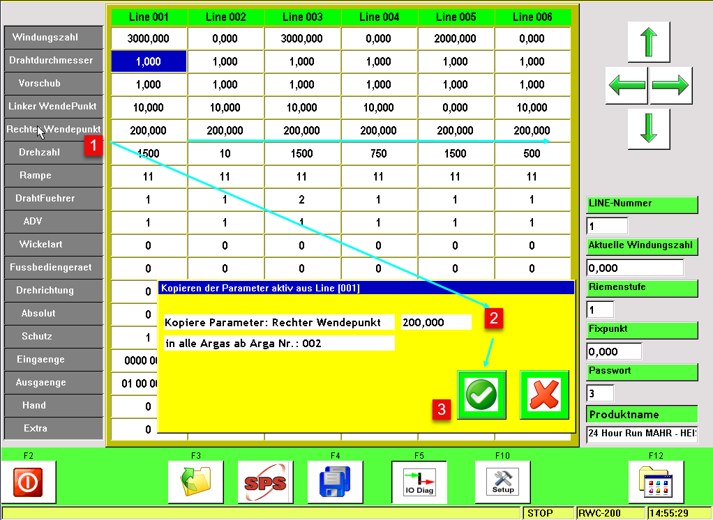 Programming page with example – copying the right reversal point
|
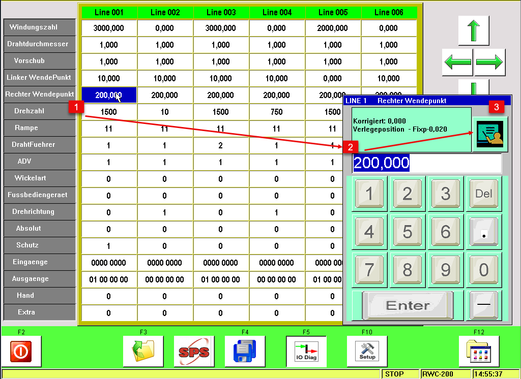 Programming page for entering all relevant winding parameters
|
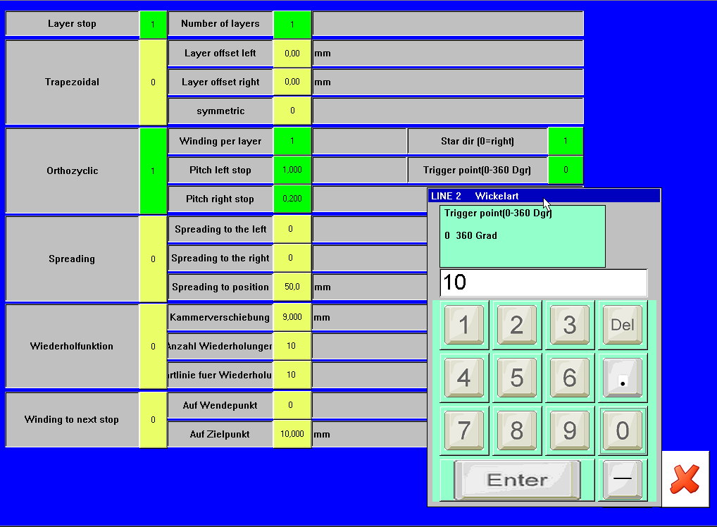 Programming functions & control, winding types extension
|
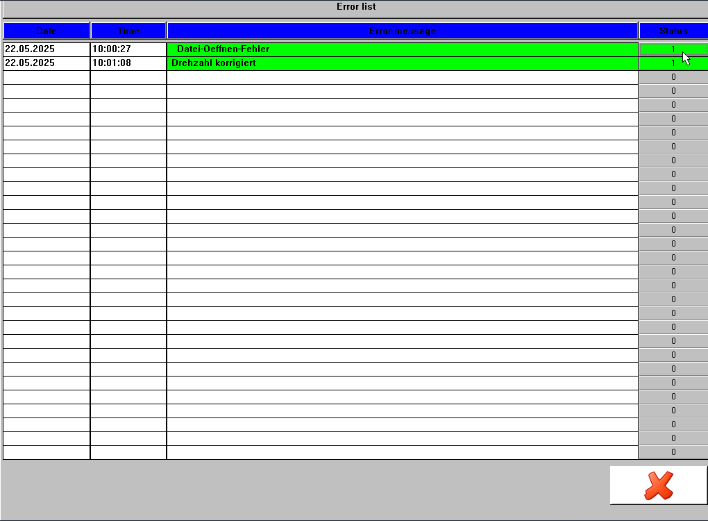 Display and acknowledgment of already corrected errors
|
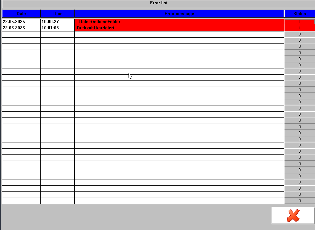 Overview of active error messages
|
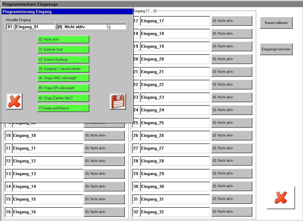 INPUTS: Configuration of programmable inputs and outputs with various options
|
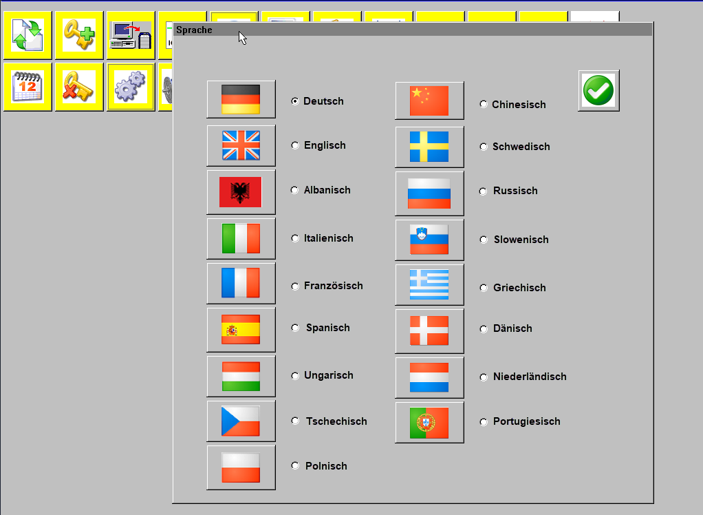 Language switching – also supports Cyrillic and Chinese
|
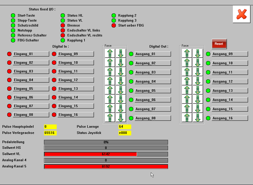 I/O diagnostics incl. forcing function, status queries, and live diagnostics
|
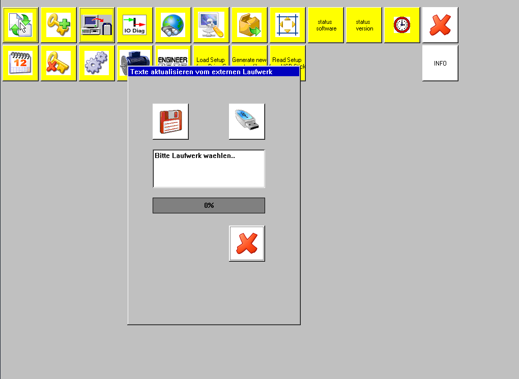 Language texts for individual adaptation of interface texts
|
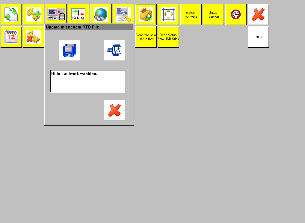 System update function for software maintenance
|
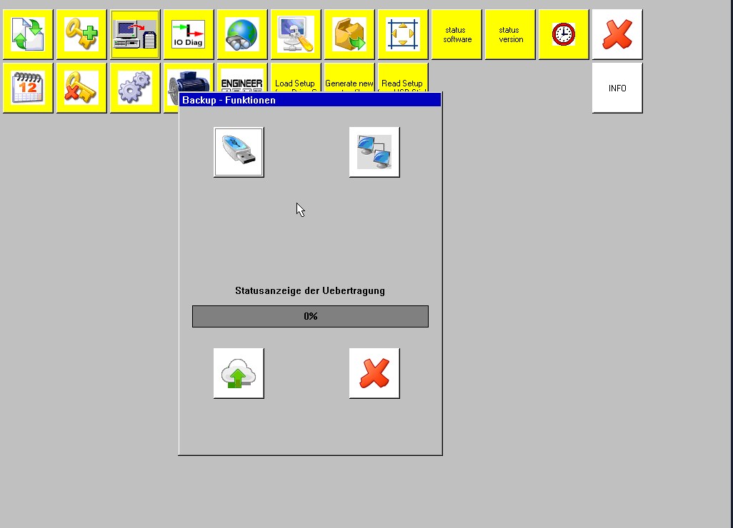 Backup function
|
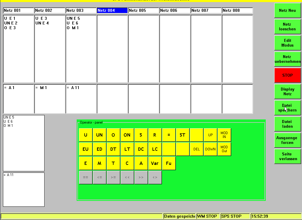 PLC integration for external control and data exchange
|
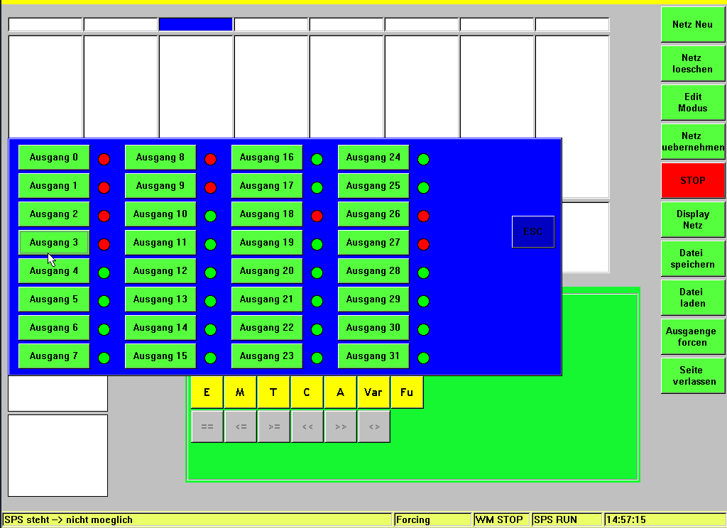 PLC integration incl. I/O forcing, status monitoring, and live diagnostics
|
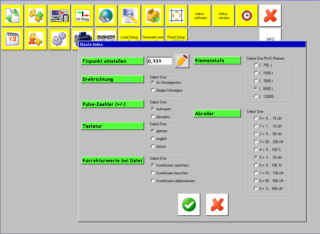 System settings – basic info
|
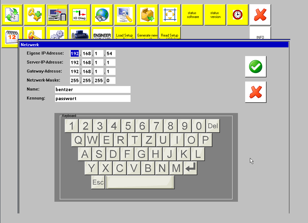 Network settings
|
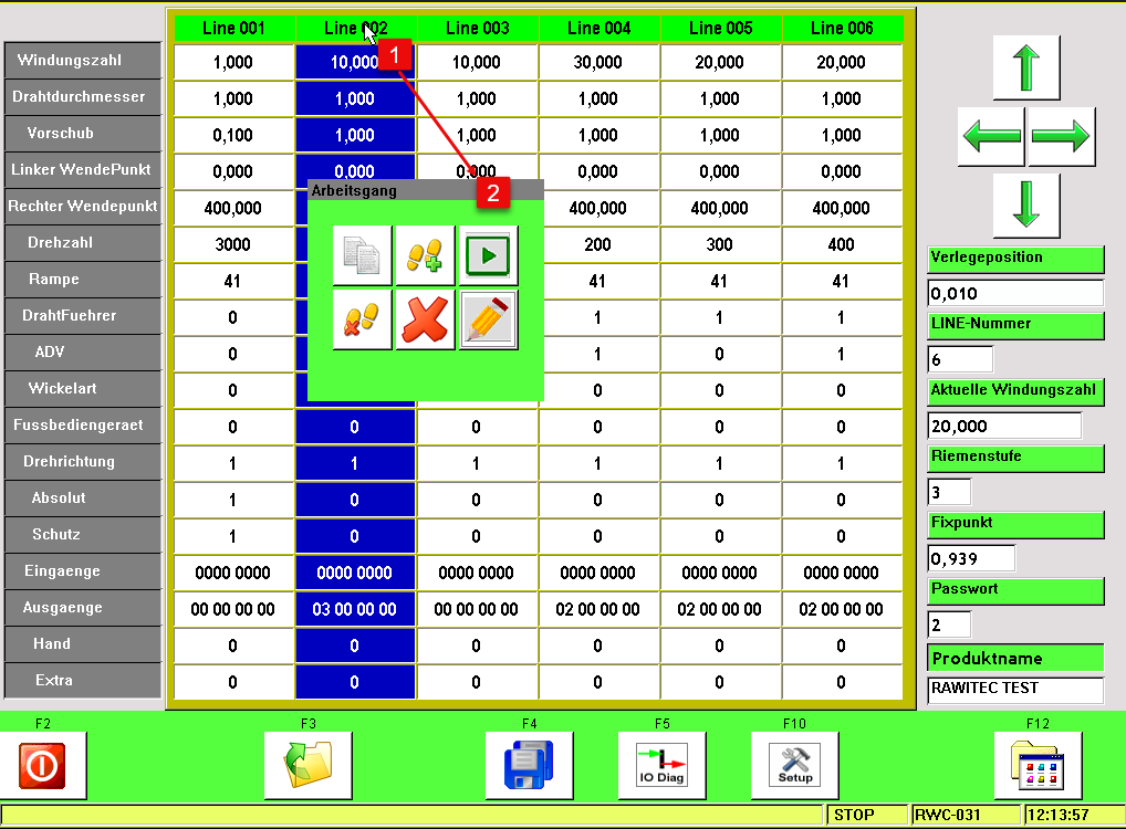 Process step management
|
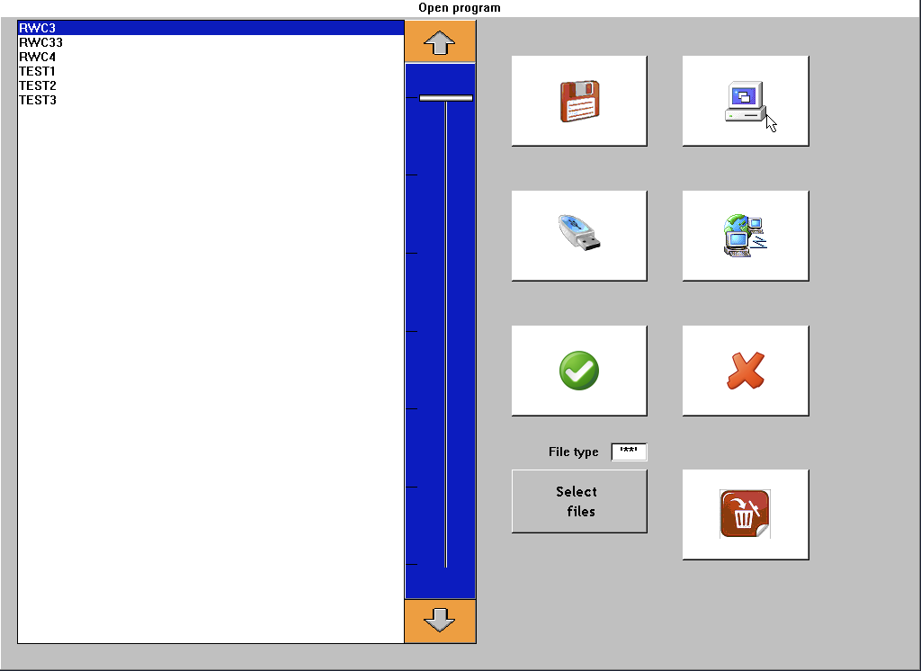 This interface allows users to open winding programs from various storage sources: internal iSATA drive, USB stick, network drive (FTP server), or USB floppy disk drive.
|
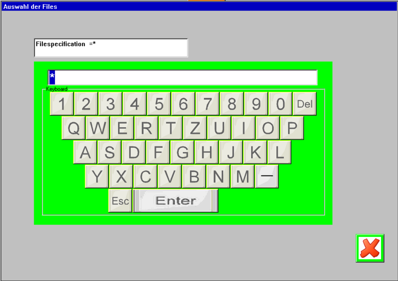 As the number of stored programs increases over time, a built-in search function helps streamline selection. By entering the first three characters, the program list is automatically filtered to show relevant matches.
|
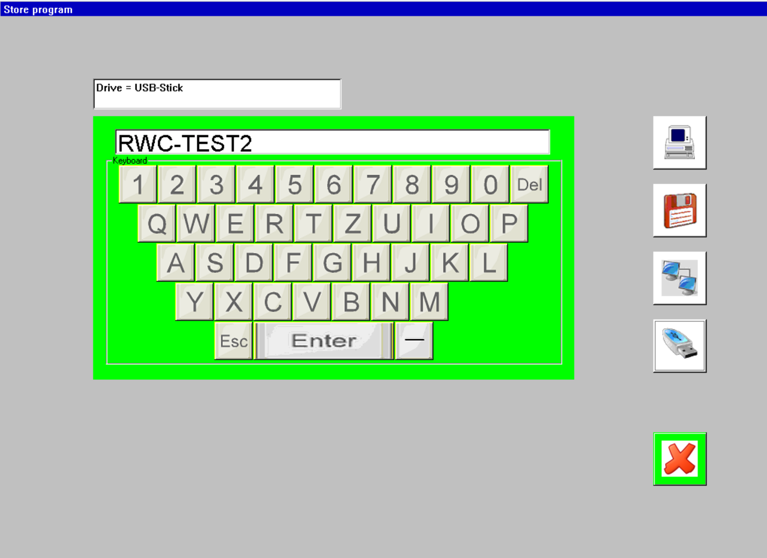 Programs can also be saved to all of the above storage media, internal iSATA drive, USB stick, network (FTP), and floppy disk drive.
|
FOG Technology & Quadrupole Winding – Precision at the Core
Fiber Optic Gyroscopes (FOG) are extremely precise inertial sensors based on the interference of light in coiled optical fibers.
They detect rotational movements in up to three axes – fully contactless and without moving parts.
In safety-critical applications where mechanical systems may fail, FOG technology offers:
- ✅ exceptional reliability
- ✅ long-term stability
- ✅ immunity to magnetic fields, vibrations, and temperature fluctuations
🔄 Quadrupole Winding – for Maximum Signal Integrity
The core of every FOG system is one or more precisely wound optical fibers. Light travels in opposite directions
within the fiber to determine the rate of rotation via interference. The winding geometry plays a crucial role:
Quadrupole windings compensate for systematic errors like thermal drift or mechanical
strain – purely through geometry.
The result:
- ➔ significantly improved angular resolution
- ➔ enhanced signal integrity
- ➔ maximum thermal stability – especially for compact high-performance sensors
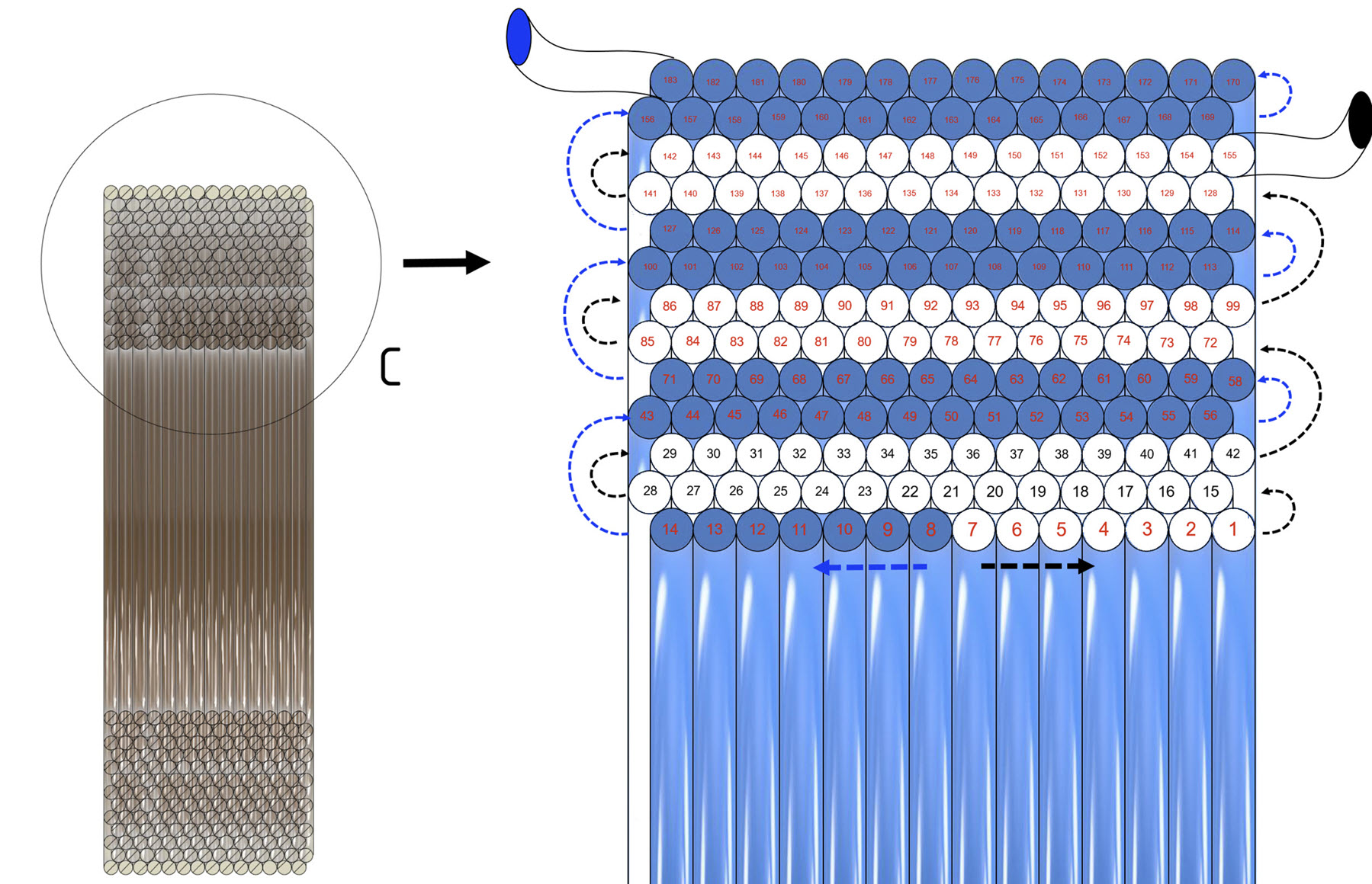 Quadrupole winding process
|
🌐 Three-Axis Systems – Precision in Every Dimension
To achieve full spatial detection, three orthogonally arranged fiber coils are used.
Each coil measures rotation along one spatial axis (X, Y, Z). The precision of the winding directly determines system performance.
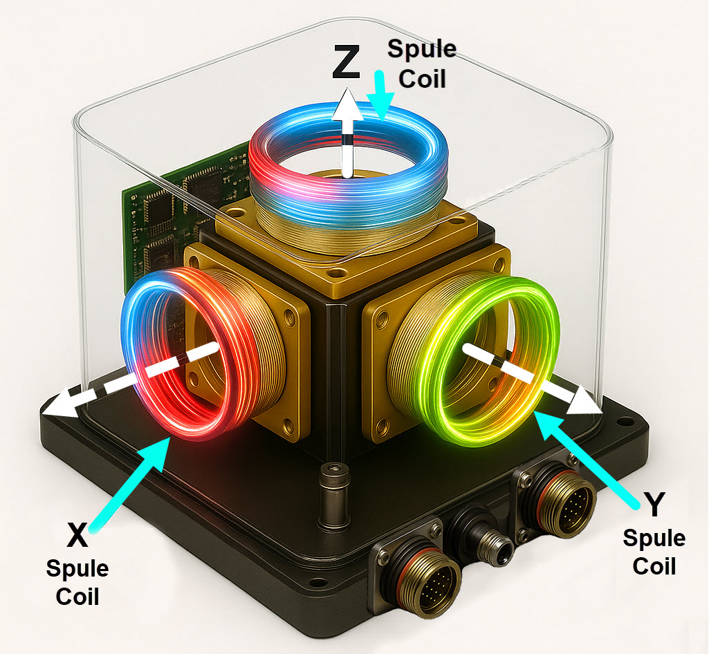 FOG system – winding application
|
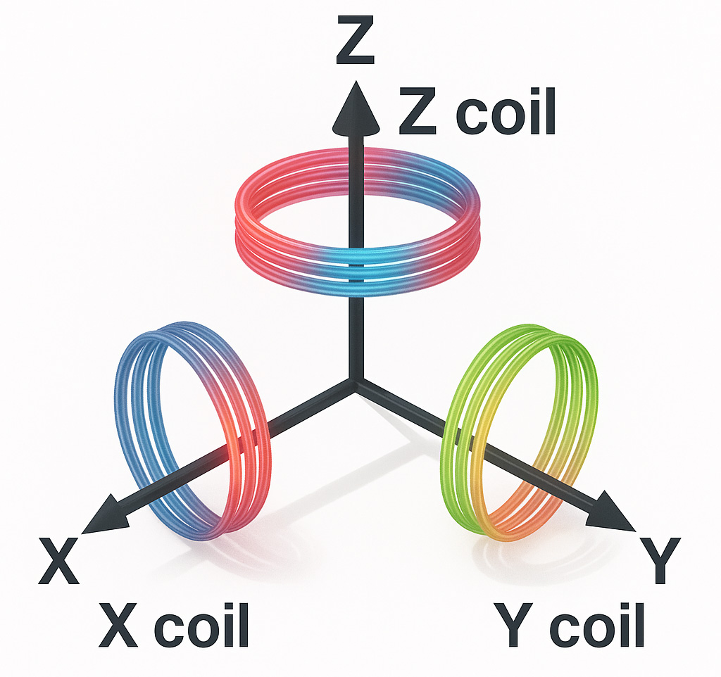 Orthogonal fiber coil arrangement in a three-axis FOG system
|
🧱 Typical Applications
- ✈️ Navigation systems for aircraft, UAVs, and guided missiles
- 🌊 Underwater positioning for submarines, AUVs, and ROVs
- 🌀 Sensing for flow, vibration, and wind tunnel testing
- 🧪 Precision coils for research facilities
- 📡 Telecommunications – e.g., delay lines, timing distribution, RF stabilization
- 📏 Fiber-optic-based sensors for strain, temperature, and structural monitoring
- 🚀 High-precision components for space, defense, and industrial applications
⭐ Your Benefits at a Glance
- Highest winding precision – micrometer-accurate layer guidance for precise measurement results
- Innovative technology – rotating spindles with dancer control, real-time monitoring, UV bonding systems
- Modular & flexible – expandable with laser scanning, digital I/Os, PLC interfaces
- Intuitive operation – touchscreen, joystick control, open programming interfaces
- Personalized support – from prototype development to series production integration
- Made in Germany – development and manufacturing to the highest quality standards
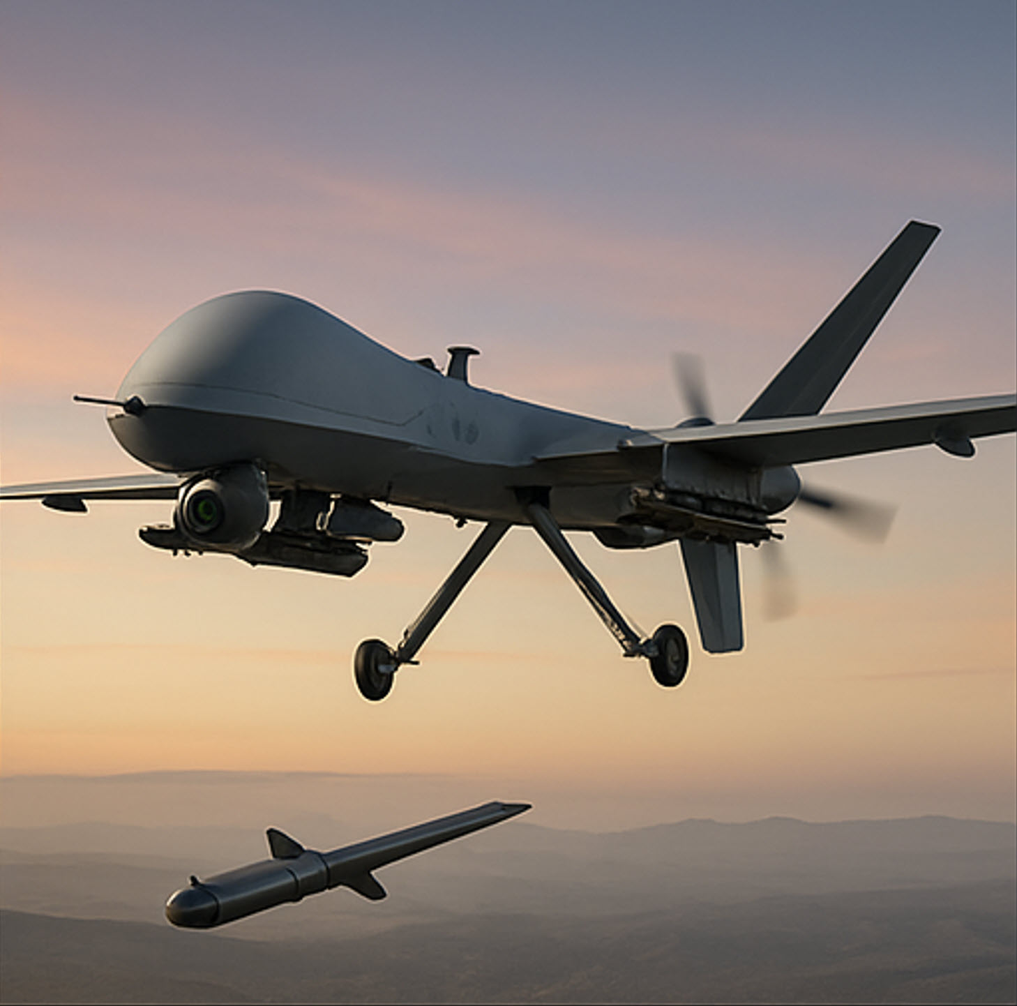 Defense & Security
|
 Aircraft
|
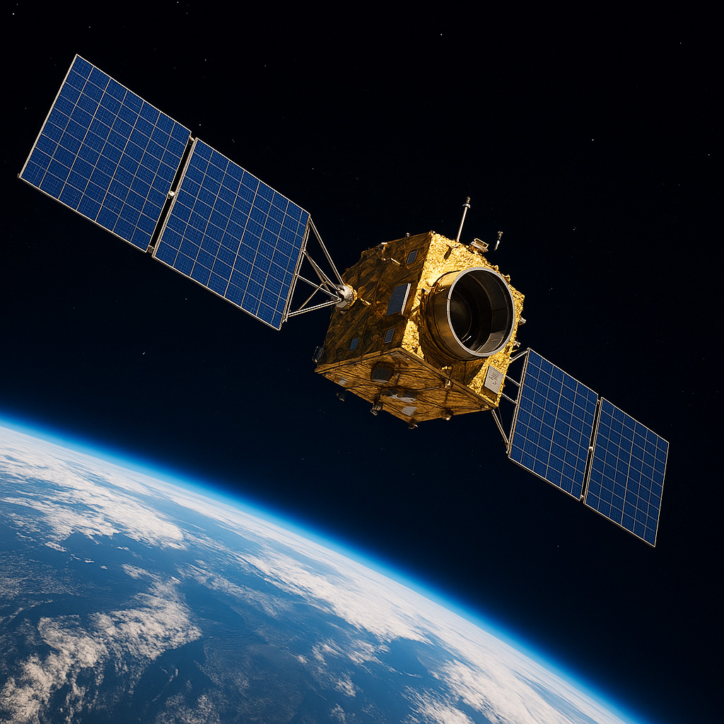 Aerospace
|
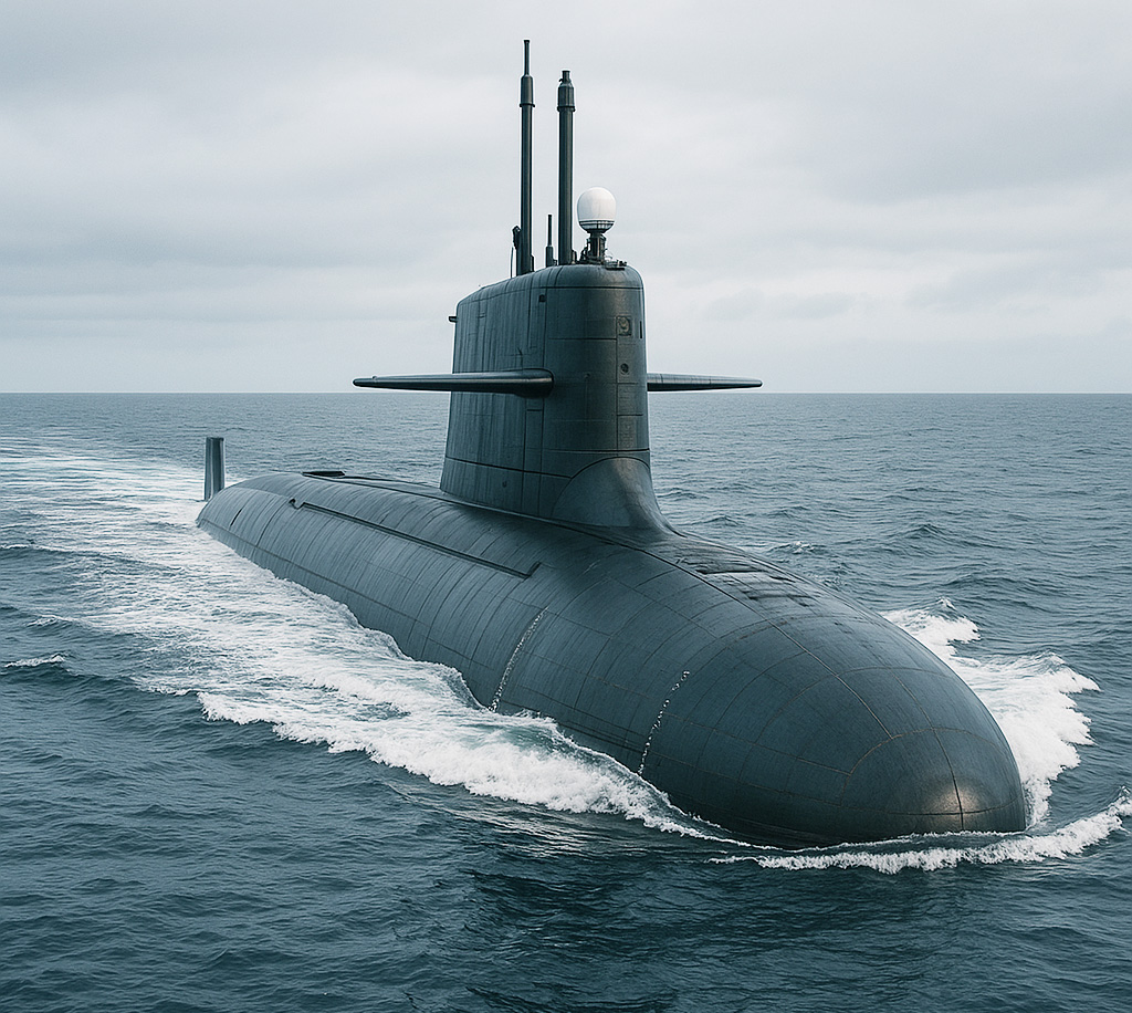 Submarines / Marine
|
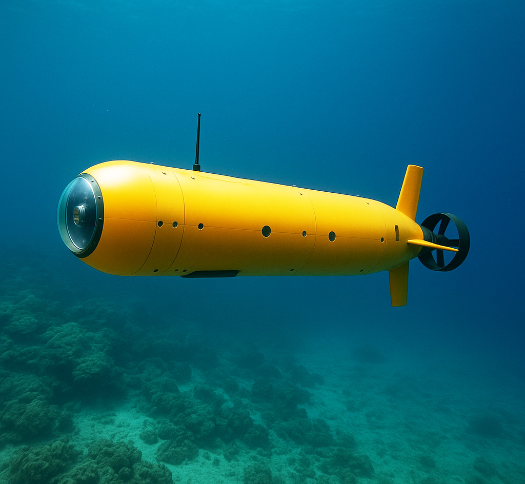 Autonomous Underwater Vehicles (AUVs)
|
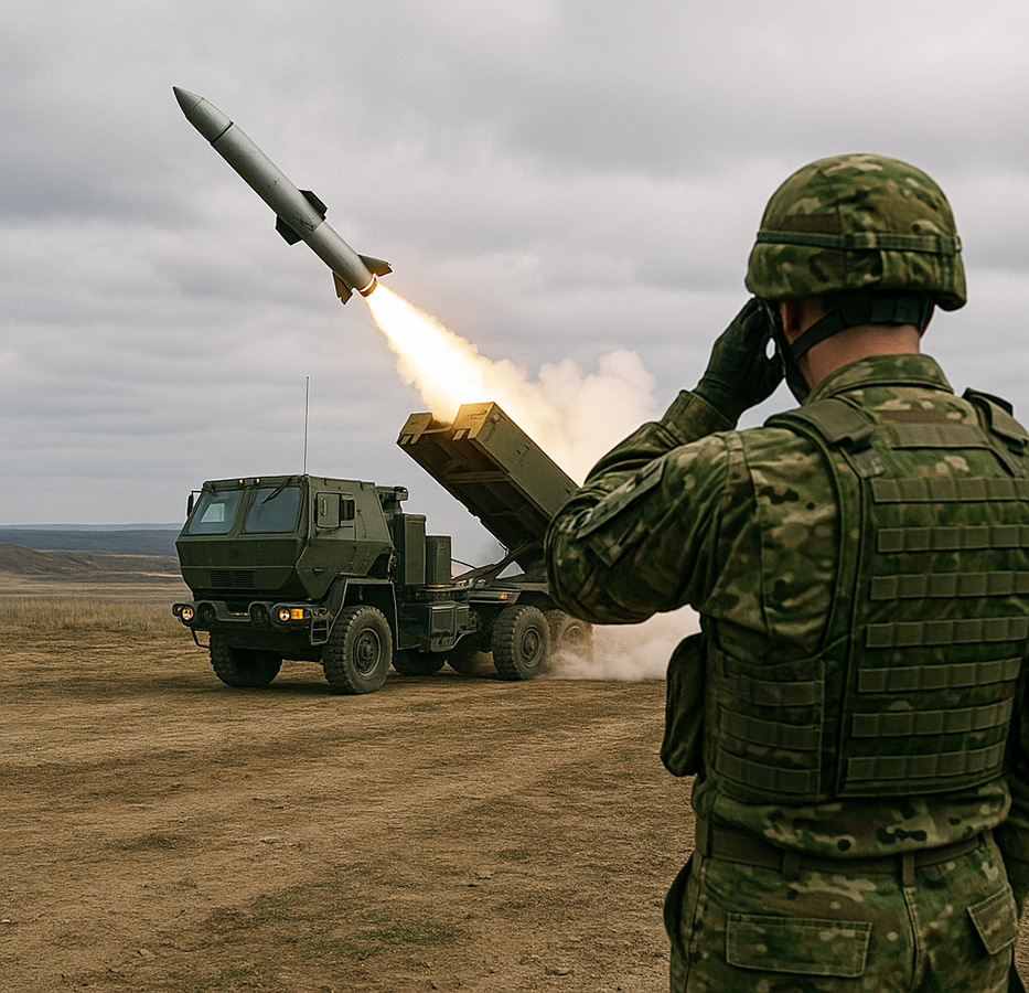 Defense & Inertial Navigation
|